Nicknamed “the Four Kings,” Raja Ampat is an archipelago located off the northwest tip of the island of New Guinea), in the Southwest Papua province of Indonesia.
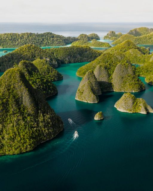
Known for the dynamic beauty of its limestone karst landscapes, Raja Ampat is made up of 1,500 small islands, cays, and shoals around 4 main islands (Misool, Salawati, Batanta, and Waigeo) and the smaller island of Kofiau.
It’s truly a nature-lover’s paradise, with forested islands, secret lagoons, beaches, bays, and the blue river of Kali Biru, all surrounded by some of the planet’s most biodiverse marine ecosystems.
Read on for our guide to the best things to do in Raja Ampat, from island-hopping cruises and Scuba diving (or snorkeling) to the best hiking trails, waterfalls, photo spots, villages, and more!
READ MORE: The 30 Best Exotic Islands in the World to Visit
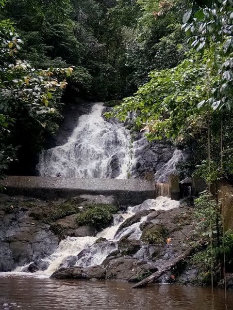
1. Chase Waterfalls
With all due respect to TLC, chasing waterfalls is one of our favorite pastimes when we travel. And the jungles of Raja Ampat offering several spectacular beauties that are well worth a visit!
The Batanta Waterfall on Batanta Island requires a bit of an arduous trek to reach it. But there’s a smaller waterfall along the way and an 80-meter cascade at the top, with a pool at the bottom to soak in and a hidden cave behind the falls.
Located on the western tip of Waigeo Island, the Warengkris Waterfall is wider than it is tall, cascading down a sheer rock face into a cool pool that’s perfect for swimming.
“Air Terjun Malol” (a.k.a. Malol Waterfall) is a beautiful waterfall with five stages located near the Gamta Village on Misool Island. It takes 1 hour on the Gamta River by boat and a 1-hour trek through the forest to reach it. But the beautiful birds along the way and the gorgeous views of this unspoiled paradise are absolutely worth it!
READ MORE: 25 of the World’s Biggest Waterfalls (By Continent)
2. Enjoy a Cruise Through the Raja Ampat Islands
We’ve explored some of the world’s best archipelagos, from the Antilles (Caribbean), Cyclades (Greek), and Galapagos to the Hebrides (Scotland), Philippines, and Society Islands of Tahiti.
One thing we’ve learned is that small ship cruises are the best way to see them, offering a low-impact way to explore island chains spread across a fairly wide geographical area.
Whether you’re looking for a no-frills, budget-friendly option or a more amenities-filled Raja Ampat luxury cruise, there are lots of different tour operators in the region to choose from.
We personally look for eco-friendly cruise companies with upscale ships that carry less than 100 passengers, who offer a nice mix of nature, wildlife, adventure, great food, and downtime for relaxation.
Note that the best time of year for taking Raja Ampat cruises is from December to February.
READ MORE: The 10 Best River Cruises in the World
3. Go Scuba Diving in the Misool Marine Reserve
As certified Scuba Divers since 2012, we’ve been blessed with opportunities to dive all around the globe, from Belize, Curaçao, and Norway to the Philippines, the Red Sea, and Tahiti.
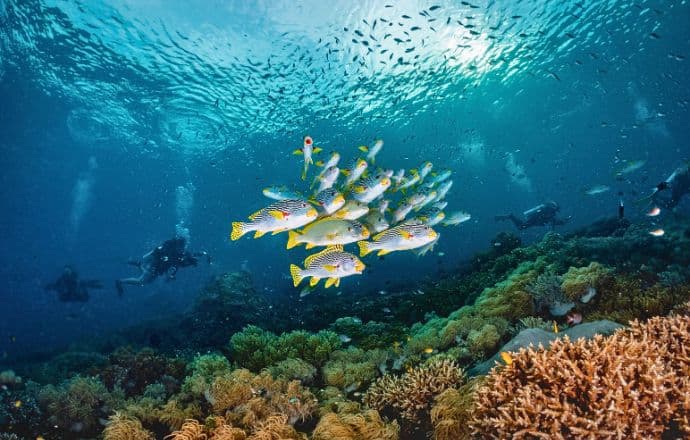
Raja Ampat is widely regarded as one of the best places in the world for Scuba diving, with unspoiled reefs that are home to 75% of the world’s known coral species (more than 10 times the diversity found in the Caribbean islands).
Working in partnership with WildAid, the Misool Marine Reserve protects complex coral reef systems and deep water areas that are home to nearly 1,500 species of fish, including manta rays, iridescent parrotfish, and schools of yellowback fusiliers.
Located in the remote southern reaches of the Indonesian archipelago, the reserve spans 300,000 acres, which are protected by the Misool Foundation‘s array of community-driven conservation programs.
Cape Kri, located near Kri Island, actually holds the world record for the most fish species seen in a single dive—374– and boasts a vividly stunning coral reef system that you have to see to believe.
READ MORE: The 20 Best Caribbean Islands to Visit For Nature Lovers
4. Hike to See Birds of Paradise
Mary’s favorite t-shirt reads “Birds Are AWESOME!” and she has 3 different kinds of feeders outside our living room window (not to mention 2 gardens full of pollinator-attracting flowers). Seeing fine-feathered friends is something we both enjoy.
From Sanibel Island FL and the Galapagos Islands to the Peruvian Amazon, we’ve taken many trips where birdwatching was a major focus. But we’ve never had the pleasure of seeing birds-of-paradise, outside of the BBC’s Planet Earth.
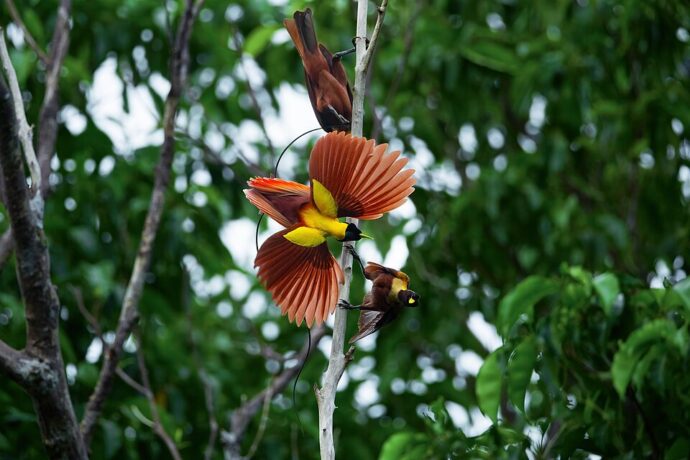
The majority of these beautiful birds are found in Australia, Papua New Guinea, and Indonesia, where the southern coasts of Waigeo and Gam offer the best chance for sightings of two colorful species.
The red bird-of-paradise is larger, with crimson wings, emerald cheeks, yellow shoulder tufts, and purple tail feathers, while the Wilson’s bird-of-paradise has a cyan cap, red-and-black body, blue feet, and tail feathers shaped like scissor handles.
Many local guides in Raja Amat offer birdwatching tours in private trails behind their homes, but some group tours to mating areas are also available.
READ MORE: 25 Spectacular Galapagos Birds You Can See on a Galapagos Cruise
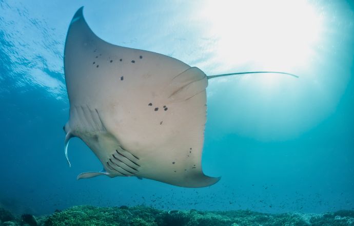
5. Swim with Manta Rays at Manta Sandy
The first time I saw a Manta Ray in the wild was while swimming with Whale Sharks in Cancun, and I was blown away by how MASSIVE these rays are in real life!
Manta Sandy, which is located in Raja Ampat between Arborek and Gam Islands, is a cleaning station that attracts Manta Rays all year round. So you can dive or snorkel and watch them gliding, completely unconcerned with human presence.
Local guides are always there to ensure that everyone behaves responsibly. Because this site is located in a protected marine reserve, chasing or touching them is strictly forbidden.
Trust me, swimming with Manta Rays is an experience you’ll never forget, and this is one of the few places in the world where you’re virtually guaranteed to have an opportunity to see them up close.
READ MORE: Swimming with Sharks in Bora Bora, Tahiti
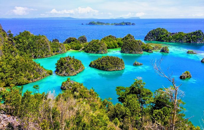
6. Take Fabulous Photos From Pianemo Hill
It seems like every major tourist destination in the world has its own iconic photograph, whether it’s the blue-domed buildings in Santorini, the ancient city of Petra in Jordan, or the volcanic peaks at the center of Bora Bora, Tahiti.
In Raja Ampat, that “must-have” photo can be found from a platform at the top of Pianemo Hill, which requires climbing around 250 steps leading up through gum trees and other dense vegetation.
Pianemo Hill is located in the Fam Islands, between Batanta and Waigeo. Ascending the summit leads you to an amazing scenic viewpoint, overlooking the 5 points of a star-shaped lagoon.
It’s the perfect place for snapping stunning shots of Raja Ampat’s dynamic karst landscape, which rises dramatically from the brilliant turquoise sea.
READ MORE: The Top 15 Things to Do in Coron, Palawan
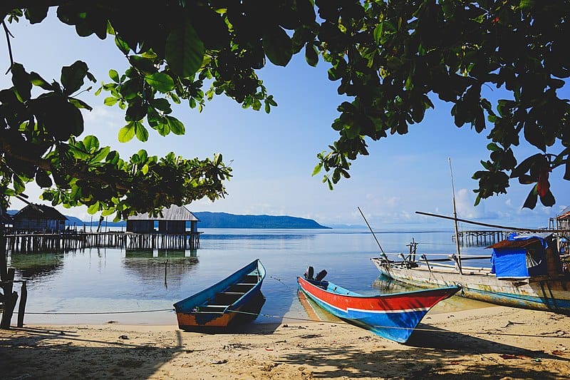
7. Visit the Local Villages
Engaging with (and spending money in) local communities is a huge principle of the ecotourism ethos, and Raja Ampat has many little villages that offer a chance to engage with the locals.
Located on an island off the coast of Waigeo, tiny Arborek Village gives visitors a chance to experience traditional Papuan culture, from music and dancing to woven crafts in the shape of the beloved marine life found just off its shores. It’s also a great place for snorkeling and Scuba diving.
Sawinggrai Village on Gam Island offers welcoming Papuan hospitality, community-based conservation, and a chance to see the Red Bird-of-Paradise. Visitors are often welcomed with traditional dances by schoolchildren, and locals love to share the ways they help protect their pristine ecosystems.
Picturesque Yenbuba Village on Mansuar Island is another fantastic place to engage with locals. It’s beloved for some of the best snorkeling in the region, lovely pastel houses, an adorable church, and some of the most welcoming Papuan people you’ll ever meet! –by Bret Love
greenglobaltravel.com (Article Sourced Website)
#Raja #Amat #Indonesia